You’re deep in your project when everything stops. You just need a clean Type 2 CAD model.
But Google gives you a junk drawer of hobby uploads, broken meshes, and sketchy repositories that all look the same. You click through a dozen promising results, and each one either has the wrong dimensions, comes in an unusable format, or simply won’t download.
The real anxiety isn’t the search itself. It’s downloading something with wrong dimensions and losing an entire day. Maybe more. You’ve got deadlines breathing down your neck, and you’re stuck on something that should take five minutes.
Here’s our path forward: We’ll figure out what Type 2 actually means, find the right file fast, and vet it in seconds so you can get back to work that matters. No more wasted afternoons. No more guessing if the model’s any good.
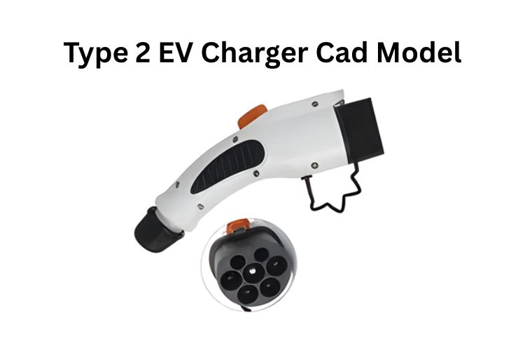
Keynote: Type 2 EV Charger CAD Model
Type 2 (IEC 62196-2) connectors dominate European AC charging with seven-pin architecture supporting 22 kW three-phase power. Engineers need STEP format files from manufacturers like Phoenix Contact or TE Connectivity for dimensional accuracy. Verify critical dimensions: 63 mm plug shroud, 65 mm socket shroud. Free community models work for accessories but require validation. Commercial projects demand certified models with proper licensing. Integration requires attention to NEC Article 625 grounding, ADA clearances, and thermal management.
First Things First: What “Type 2” Actually Means (So Your Model Matches Reality)
The Official Definition You Need to Know
Type 2 equals IEC 62196-2 AC connector, Europe’s baseline for public charging inlets and plugs. This isn’t just another industry acronym to memorize. It’s the specification that ensures every EV in Europe can plug into every public charger without an adapter.
Seven pins do the heavy lifting: L1 through L3, neutral, protective earth, plus PP and CP for signaling and safety. The first five handle the power delivery, delivering up to 22 kW of three-phase AC power at 63 A. The PP (Proximity Pilot) tells the vehicle what cable ampacity you’ve got before charging begins. The CP (Control Pilot) is the constant handshake during the entire charge session, negotiating the charging level through PWM duty cycle communication.
Think of it like this: the power pins are the highway, and the control pins are the traffic signals making sure everything flows safely.
Why This Matters Beyond Europe
The EU made Type 2 the public AC standard, and CCS2 extends it for DC fast charging worldwide. What started as a European mandate has become a global reference point.
If your project touches EV infrastructure anywhere, you’re likely dealing with this connector or its DC cousin. The Type 2 geometry forms the upper, AC-capable portion of the CCS Combo 2 connector, which adds two large DC power pins below the standard 7-pin layout for fast charging applications. China’s GB/T standard drew inspiration from it. Even North America’s EV manufacturers are watching Europe’s Type 2 rollout closely as they build out their own networks.
This connector isn’t going anywhere. Understanding it now means you’re prepared for the next decade of EV infrastructure work.
The Emotional Gap: Why Most “Free CAD” Files Leave Engineers Anxious
The Pretty Model That Doesn’t Fit
Community uploads look gorgeous in the preview, but tolerances or pin depths turn out wrong when you test-fit them. You import the file into your assembly, spend an hour positioning everything perfectly, then discover the connector shroud diameter is off by 2 mm. Now nothing mates properly.
It’s like building with foggy Lego pieces. You can see the shape, but the details are a gamble. Sure, the overall silhouette looks right. The render is beautiful. But when you try to design the mating housing around it, suddenly you’re chasing phantom dimensions that don’t match any datasheet you can find.
Nobody warns you about this upfront. The file downloads cleanly. The preview looks professional. You only discover the problem when you’re knee-deep in your design work.
The Hidden Treasure Hunt
Supplier PDFs bury STEP and IGES files two clicks deep inside product pages you’d never find organically. You land on a manufacturer’s homepage, see a generic product overview, and assume they don’t offer CAD downloads. You move on.
Meanwhile, the file you need is sitting right there, hidden behind a “Downloads” tab on the specific part number’s product page. But you’d need to know the exact part number to get there. And to know the part number, you’d need to wade through a 200-page catalog PDF.
“Free to download” does not equal “OK for production drawings.” Licensing varies wildly and nobody warns you. That seemingly innocent model on GrabCAD might have a Creative Commons Non-Commercial license tucked away in the description. Use it in a client project, and you’ve just opened a legal liability nobody needs.
Some models explicitly forbid selling physical prints. Others require attribution that might be impractical in your documentation. The rules are all over the map, and you’re expected to be a copyright lawyer just to download a connector model.
The 30-Second Reality Check Most People Skip
Check the 3D preview and file size before you click download. A 10kb STEP file is a red flag screaming broken geometry. Real STEP models of precision connectors run at least 200-500 kb because they contain actual mathematical surface data. If the file’s suspiciously small, it’s probably just a hollow shell.
Read the comments from other engineers. “Dimensions are off” means run, “Saved me hours” means gold. When someone says “printed perfectly but had to scale it up 3%,” that’s your warning the model’s dimensionally inaccurate. When five people confirm “matches the Phoenix Contact datasheet exactly,” you’ve found treasure.
User feedback is the fastest verification you’ll get without downloading and measuring yourself. Trust it.
Where the Good Models Actually Live (And How Each Source Is Different)
The Source Landscape Snapshot
| Source | What You’ll Find | Trust Level | Typical Formats | Notes |
|---|---|---|---|---|
| GrabCAD | User-uploaded Type 2 plugs, holders, mounting brackets | Mixed | STEP, STL | Great for concepting. Always verify dimensions against datasheet and check license. |
| TraceParts | Supplier-certified EV and connector parts from manufacturer catalogs | High | STEP, IGES, Native CAD | Direct from OEM catalogs. Cross-check series and variant numbers with your spec. |
| 3DfindIT | Meta-search across 5,500+ engineering catalogs | High-mix | Many | Fast discovery tool. Click through to the original OEM catalog for full specs. |
| Phoenix Contact | Vehicle inlets (Type 2, CCS2), technical datasheets, ISO 15118 notes | High | 3D viewers, datasheets | Request STEP files per part number. They include CP, PP signaling details. |
| Mennekes | Cable and connector datasheets with ratings, IP protection, cable lengths | High | PDF (pair with CAD from catalogs) | Gold standard for dimensional accuracy. Always cross-check your CAD against their line-items. |
| ABB, Siemens, Schneider | Full charger system models and mounting specifications | High | STEP, native formats | The pro move. Manufacturers want you to design their products into buildings. Files are 100% accurate. |
Here’s the thing: where you get your model matters more than anything else. A manufacturer-certified file from Phoenix Contact is fundamentally different from a community upload on Thingiverse, even if they look identical in the preview.
Manufacturer models are digital twins of the physical part. They’re used internally for tooling and quality control. The company’s reputation depends on these files being perfect.
Community models are well-intentioned but unverified. They might be traced from photos, reverse-engineered with calipers, or modeled from memory. They’re often brilliant starting points, but they’re not engineering references.
The Starter Tactic If You’re Out of Time
Grab a supplier-certified housing today, then swap or adjust pin assemblies as your design evolves later. Don’t let perfect be the enemy of shipped. If you can’t find the exact model of the complete assembly you need, download the best housing geometry you can find from a manufacturer, and note the pin configuration in your documentation.
You can refine the internal details later when you have more time or better sources. But at least your outer envelope, your mounting holes, and your clearances will be spot-on from day one.
Always cross-reference any downloaded model against the latest datasheet before you commit it to your assembly. Print out the dimensional drawing. Measure the key features in your CAD software. Match them line by line. This ten-minute check saves days of rework.
The Format Decision That Changes Everything
A STEP or IGES file is your editable Lego block, perfect for engineering integration and modifications. These Boundary Representation (B-Rep) formats describe geometry mathematically, defining surfaces with perfect fidelity. You can measure anything. You can modify features. You can create mating parts with confidence.
An STL file is a static painting, good for 3D printing but useless for parametric design work. STL represents the surface as a triangular mesh, an approximation of the true shape. Try to measure a hole diameter in an STL, and you’re counting triangles. Try to modify a fillet radius, and you’re in for a nightmare.
For professional engineering work, always choose STEP. For sending something to a 3D printer, STL is fine. It’s that simple.
The Technical Details That Quietly Wreck Assemblies
Pinout and Signaling You Can’t Ignore
Seven pins handle up to 63 A AC, with PP doing 4.7 kΩ coding and CP handling PWM duty cycle for current limits. But these aren’t just abstract numbers in a specification. They’re real constraints that affect your mechanical design.
PP tells the vehicle what cable ampacity you’ve got. It does this through a simple resistor coding scheme on the proximity pilot contact. Before the connector is fully inserted, the vehicle reads this resistance value and knows whether it’s dealing with a 13 A, 20 A, or 32 A cable.
CP is the constant handshake during the entire charge session. It’s a 1 kHz square wave signal with a duty cycle that encodes the maximum current the EVSE can supply. The vehicle listens to this signal and adjusts its charging rate accordingly. If communication fails, charging stops immediately.
Your CAD model needs to show these pins clearly. Their location matters because you’ll be routing signals to them, and any crosstalk or poor grounding can cause charging failures.
The Grounding and Safety Reality
NEC Article 625 mandates that all non-current-carrying metal parts must bond to equipment grounding, isolated from the grounded AC conductor. This isn’t optional. It’s code.
Your CAD must show clear grounding paths and proper conductor sizing, especially for outdoor or high-power installations. That means modeling the protective earth (PE) pin connection with enough detail to show how it bonds to the station enclosure, how it routes back to the panel, and where the bonding jumpers connect.
If you’re designing a complete charging station, you need to model the grounding electrode conductor path, the connection points, and the bonding of all metallic raceways. Inspectors will look for this. If your installation drawings don’t show it clearly, you’ll fail inspection.
Clearances That Determine If Your Design Actually Works
ADA requires 36-inch-wide accessible routes and 30-by-48-inch clear floor space in front of operable parts for wheelchair access. These aren’t suggestions. They’re federal requirements in the United States, and similar standards exist worldwide.
NEC 625.29 demands 3 feet of working space in front of EVSE equipment, more if over 150V to ground. For 240V systems, which most Level 2 chargers are, that means 3 feet of clear space. For anything connected to a higher voltage system, you might need 3.5 or even 4 feet depending on the installation.
Model these keep-out zones in your CAD right now, not after the first site visit when it’s too late. Create simple box volumes in your assembly that represent the required clearances. Lock them in place. Make them bright red. Force yourself to design around them from the beginning.
You know that sinking feeling when you show up to a site and realize your charger placement won’t pass inspection? That feeling costs money. Avoid it with ten minutes of CAD work today.
The Strategic Design Choices That Separate Good from Great
The Modular Mindset for Your CAD Library
Don’t just model one charger. Build a library of interchangeable components: housings, cable management, mounting brackets. Think of it as investing in your future self.
Model the Type 2 socket once, really well, with all the correct dimensions and material callouts. Then save it as a standalone assembly. Next time you need it, you just drop it in. Model a standard wall-mount bracket as a separate part. Model cable entry glands in three different sizes. Model a standard user interface panel.
Future you, rushing on the next project, will thank present you for this investment. Building a library feels slow when you’re in the middle of a deadline crunch. But after the third or fourth project, you’ll realize you’re working three times faster than your competitors because you’re not starting from scratch every time.
The Two Architecture Paths
| The Integrated Unit (All-in-One) | The Satellite System (Power Cabinet Plus Poles) |
|---|---|
| Best for: Wall-mounted or pedestal AC chargers (Level 2). Simpler, self-contained. | Best for: High-power DC charging stations. Centralizes heavy components for dynamic power sharing. |
| Your CAD Focus: Compact internal layout, single housing design, user interface integration. | Your CAD Focus: Cabinet infrastructure, cable conduit paths, pole and connector placement across multiple stalls. |
The architecture choice fundamentally changes your CAD workflow. An all-in-one Level 2 charger is a single assembly. You model it as a unit, you test it as a unit, you install it as a unit. Everything’s in one package.
A satellite system splits into multiple assemblies: the power cabinet, the dispenser poles, the underground conduit runs. Your CAD needs to track how these pieces connect across distances, how cable routing works, how you’re sharing power between multiple charge points.
Choose your architecture early. It affects everything downstream.
Why Analysis Tools Are Your Secret Weapon
Use your CAD software’s built-in simulation to analyze heat dissipation from power electronics and stress on attached cables. Most modern CAD packages include basic thermal and structural analysis. They’re not full-blown finite element packages, but they’re good enough to catch obvious problems.
A ten-minute thermal flow check can save you from a redesign after the first hot summer day in operation. Model the heat sources (your power electronics), set up the convection boundary conditions (ambient air at 40°C), and run the simulation. If your components are hitting 90°C when the spec limit is 85°C, you know you need better ventilation or a larger heat sink.
Better to discover this on your screen than in the field after 50 units are already deployed.
The Human Layer: Where Engineering Meets Real-World Experience
The Cold Grab Test
Imagine a user handling your connector on a freezing morning with gloves on. Does the grip diameter and texture work? You’ve optimized the electrical design. You’ve verified every dimension. But can someone actually use this thing when it’s 15°F outside and they’re wearing winter gloves?
Model for everyone, not just for a climate-controlled lab environment. Weight, balance, and tactile feedback all matter. The Type 2 connector with its cable attached weighs several pounds. Hold that weight at arm’s length while trying to align pins. Now imagine doing that in the rain, in the dark, when you’re tired and just want to get home.
Good design acknowledges this reality. Bad design ignores it.
The Digital Handshake Behind the Scenes
Your charger lives in a network. It must accommodate communication modules (4G, Ethernet) for OCPP, managing authentication and smart charging. The connector might be analog, but the station around it is increasingly digital.
OCPP (Open Charge Point Protocol) means your charger talks to a backend server. It reports session data, receives pricing updates, handles remote start commands, and downloads firmware updates. All of that requires communication hardware with its own space requirements, thermal management needs, and mounting provisions.
Plan space for these modules early, or you’ll be retrofitting boxes onto finished designs. Reserve a volume in your enclosure CAD model. Label it “Comm Module – TBD.” Provide mounting holes on standard spacing. Leave room for antenna routing. These little details save enormous headaches later.
The Three-Second Interface Test
Stress-test your UI model in sun glare and total darkness to ensure screen readability and button feedback are flawless. This means taking your CAD model, adding a simulated screen at the actual installed height, and checking sight lines. Can a driver see it from their car? Can a wheelchair user reach it? Is it readable at noon with the sun directly overhead?
If a tired driver can’t figure it out in three seconds at midnight, your interface has failed. Three seconds is the attention span you get. The user is distracted, maybe on their phone, maybe wrangling kids in the backseat. Your interface needs to be instantly obvious.
Button press confirmation is tactile, not just visual. Model the buttons with enough travel to give physical feedback. Specify materials with the right durometer. These details seem minor until someone’s using your charger in the real world, wondering if their button press registered.
When You Can’t Find the Perfect Model (The “Good Enough” Strategy)
The Context That Makes This Work Matter
You’re not alone in this hunt. EV charging ports are projected to grow to over 40 million globally by 2030. That’s up from maybe 2 million in 2020. This is one of the fastest infrastructure buildouts in modern history.
This infrastructure buildout is happening now. Your design work is part of something massive. Every charging station you help design enables someone’s transition away from fossil fuels. Every clearance dimension you get right makes charging accessible to more people. Every thermal analysis you run improves reliability for thousands of charging sessions.
The work matters. And that means doing it right matters.
The Placeholder That Saves Projects
Sometimes perfect is the enemy of done. Find the official PDF spec sheet from the manufacturer. It always has dimensions. The datasheet might not include a 3D STEP file, but it will have dimensional drawings. Front view, side view, top view, with all the critical dimensions called out.
Model a simple keep-out box with correct dimensions. Often that’s genuinely all you need for layout and clearance work. You don’t need perfect pin geometry if you’re just planning where chargers go on a site plan. You don’t need exact surface textures if you’re verifying minimum approach distances.
A simple box with the right outer envelope gets you 80% of the value in 10% of the time. Use it. Move forward. Refine later when you have better data or more time.
When to Just Ask Your Supplier
If you’re specifying a real charger for a real project, email your supplier directly. They have these files ready. Seriously. If you’re about to place a purchase order for 50 charging stations, the manufacturer will absolutely send you CAD files.
This five-minute email can end hours of frustrated searching. The person in sales or technical support has a folder on their computer labeled “CAD Files for Customers.” They send these files out every day. You’re not imposing. You’re being a good customer by doing your due diligence before purchasing.
Don’t be shy about asking. “Hi, I’m evaluating your Model XYZ charger for a commercial installation. Do you have STEP files available for site planning?” That’s all it takes.
Conclusion: Get the Right File and Get Back to What You Do Best
Recap the journey: You started with that sinking feeling of being stuck on something that should be simple. We cut through the noise together by understanding what Type 2 actually means, where the reliable files hide, how to spot junk in seconds, and why the human and technical details both matter deeply.
You learned that manufacturer-direct sources beat community uploads for professional work every time. You discovered that STEP files are non-negotiable for engineering, while STL is fine for printing brackets. You found out that dimensional validation takes minutes but saves days. And you realized that clearances, grounding, and user experience aren’t afterthoughts, they’re fundamental design constraints that need to be in your CAD model from the start.
You’re not hunting files anymore. You’re equipped.
Your one action for today: Open your current project right now and perform a virtual reach analysis from the driver’s side of a vehicle with the charging inlet on the front fender. Set up a simple human mannequin in your CAD software, position it as if standing next to a parked car, and verify they can comfortably reach your charger location. You’ll learn more about real-world usability in ten minutes than in weeks of guessing.
Your final thought: The future of EV infrastructure isn’t just about building more chargers. It’s about building better ones that work for everyone, in every condition, from day one. And that future starts on your screen, right now, with the work only you can do.
Type 2 EV Charger Cad Models (FAQs)
What CAD file format is best for EV charger design?
Yes, STEP format is best for professional EV charger design work. It preserves exact geometric precision using mathematical surface definitions. This allows accurate measurements, feature modifications, and assembly constraints.
STEP files ensure your connector models match physical parts within manufacturing tolerances. IGES is an older alternative, while STL only works for 3D printing.
Where can I download free Type 2 connector CAD models?
No single best source exists. For professional engineering, start with manufacturer portals like Phoenix Contact, TE Connectivity, or TraceParts for certified models. For 3D printing holders and accessories, check Printables, Thingiverse, or GrabCAD. Always verify dimensions against IEC 62196-2 datasheets regardless of source. Free doesn’t mean accurate or commercially licensed.
How do I verify CAD model accuracy against IEC 62196-2 specs?
Yes, verify key dimensions using your CAD measurement tools before integration. Check that the plug shroud diameter measures 63 mm and socket shroud measures 65 mm. Confirm all seven pins are present and correctly positioned. Cross-reference the 3D model against manufacturer 2D technical drawings. For critical applications, compare measurements against the official IEC 62196-2 standard document.
What’s the difference between STEP and IGES for charging station design?
STEP is the modern industry standard and generally preferred for charging station design. Both formats use mathematical boundary representation for precise geometry, but STEP handles complex assemblies and metadata better. IGES is an older format with limited assembly support. For new projects, always request STEP files when available. Only use IGES if STEP isn’t offered.
Can I use free CAD models for commercial manufacturing projects?
No, not automatically. Check the license terms carefully before commercial use. Many GrabCAD and Thingiverse models have Creative Commons Non-Commercial restrictions.
Manufacturer-provided models are implicitly licensed for integration into products using their components. For commercial manufacturing of connector housings themselves, you need properly licensed models or must create original designs.